Difference between revisions of "Getting Started With PIC(TM) MCU"
PaoloVilla (Talk | contribs) |
PaoloVilla (Talk | contribs) |
||
| (9 intermediate revisions by the same user not shown) | |||
| Line 1: | Line 1: | ||
!!!___WORK_IN_PROGRESS___!!! | !!!___WORK_IN_PROGRESS___!!! | ||
| + | |||
| + | |||
| + | NOTE: | ||
| + | This is not a replacement for the microcontroller datasheet, reference manual and programmer’s manual published by Microchip | ||
| + | Technology. It is also not a replacement for the MPLAB C30 compiler user’s guide, and all the libraries and related software | ||
| + | tools offered by Microchip. Should you notice a conflict between this document and the official documentation, ALWAYS refer | ||
| + | to the latter. | ||
| Line 7: | Line 14: | ||
=== Chosing a PIC(TM) Microcontroller === | === Chosing a PIC(TM) Microcontroller === | ||
| − | The first step to | + | The first step to chose a microcontroller is to focus on hardware/software needs: |
* Board power supply is 3V or 5V (or other)? | * Board power supply is 3V or 5V (or other)? | ||
* Power saving is crucial? You need a Ultra-Micro-Low-Nanowatt-Power microcontroller? | * Power saving is crucial? You need a Ultra-Micro-Low-Nanowatt-Power microcontroller? | ||
* Application need a little, low cost microcontroller (8bit MCU), a bigger, high performance 16bit MCU or an exagerated 32bit microcontroller? | * Application need a little, low cost microcontroller (8bit MCU), a bigger, high performance 16bit MCU or an exagerated 32bit microcontroller? | ||
| − | * What kind and how many peripherics are needed in your application? ADC, UART, Timers, PWM Channels, | + | * What kind and how many peripherics are needed in your application? ADC, UART, Timers, PWM Channels, stackable Interrupts, SPI, I2C, Can Bus, Ethernet, USB... Yes, it's not a joke! High Performance PIC Microcontroller can have one or more USB and/or Ethernet port, you can implement usb mass storage or TCP-IP functions. |
| − | TCP-IP functions. | + | |
* Available memory space: you need an extra large memory because you just know your firmare will be extra long? | * Available memory space: you need an extra large memory because you just know your firmare will be extra long? | ||
| − | Once you have answered some of these questions you can use Microchip Advanced Parts Selector (MAPS(TM)) to find only microcontrollers that satisfy your | + | Once you have answered some of these questions you can use Microchip Advanced Parts Selector (MAPS(TM)) to find only microcontrollers that satisfy your requirements. |
| − | + | ||
MAPS is available on-line or for download directly from Microchip web site (http://www.microchip.com). | MAPS is available on-line or for download directly from Microchip web site (http://www.microchip.com). | ||
| Line 35: | Line 40: | ||
Besides a PC, because of we intend "make" something and not only talk about it, we need some hardware tools: | Besides a PC, because of we intend "make" something and not only talk about it, we need some hardware tools: | ||
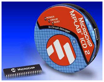
| − | * PIC MCU programmer-debugger (in Ai&R Lab Lambrate you can find some Microchip ICD2(TM) programmer-debugger, some adapter boards with ZIF socket and some | + | * PIC MCU programmer-debugger (in Ai&R Lab Lambrate you can find some Microchip ICD2(TM) programmer-debugger, some adapter boards with ZIF socket and some self-made programming cables); |
| − | self-made programming cables); | + | |
* PIC MCU demoboard or your board with power supply, PIC Microconroller, oscillator, MCLR circuitry and some input-output hardware. | * PIC MCU demoboard or your board with power supply, PIC Microconroller, oscillator, MCLR circuitry and some input-output hardware. | ||
| + | |||
| + | [[Image:ICD2.jpg]] | ||
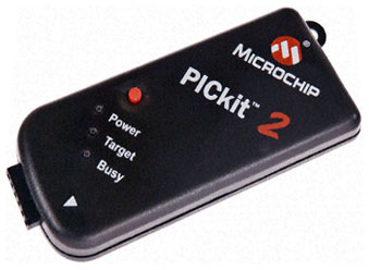
If you are watching to buy an own programmer/debugger, Microchip PIC-KIT could be the right choise due to it's little dimensions, low price and good | If you are watching to buy an own programmer/debugger, Microchip PIC-KIT could be the right choise due to it's little dimensions, low price and good | ||
performances. For detailed information, including PIC microcontroller supported list, visit microchip web site. | performances. For detailed information, including PIC microcontroller supported list, visit microchip web site. | ||
| + | |||
| + | [[Image:PicKit.jpg]] | ||
| Line 50: | Line 58: | ||
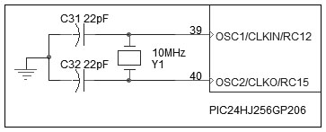
* Internal Oscillator (in general an internal RC network); | * Internal Oscillator (in general an internal RC network); | ||
* External Oscillator (external clock source, external crystal or ceramic resonator operation and external RC network). | * External Oscillator (external clock source, external crystal or ceramic resonator operation and external RC network). | ||
| − | |||
[[Image:MCUOscillator.jpg]] | [[Image:MCUOscillator.jpg]] | ||
| Line 83: | Line 90: | ||
application. The ICSP interface uses two pins as its core. | application. The ICSP interface uses two pins as its core. | ||
The programming data pin (PGD) functions as both an input and an output, allowing programming data to be read in and device information to be read out | The programming data pin (PGD) functions as both an input and an output, allowing programming data to be read in and device information to be read out | ||
| − | on command.The programming clock pin (PGC) clocks in data and controls the overall process. | + | on command. The programming clock pin (PGC) clocks in data and controls the overall process. |
Serial programming allows customers to manufacture boards with unprogrammed devices and then to program the digital signal controller just before shipping | Serial programming allows customers to manufacture boards with unprogrammed devices and then to program the digital signal controller just before shipping | ||
| Line 124: | Line 131: | ||
=== MPLAB IDE settings === | === MPLAB IDE settings === | ||
| − | + | Select in "Debugger" menu the programmer/debugger device you have to use (probably "1 MPLAB ICD 2", if you are working on AI&R Lab...) | |
| + | [[Image:MPLAB_Debugger_Menu.jpg]] | ||
| − | === | + | To verify if programmer/debugger is connected to your Pc, to PIC microcontroller and is ready to operate select "Settings" in "Debug" menu and than pres |
| + | "Run Self Test" in the just opened window: | ||
| + | |||
| + | [[Image:MPLAB_ICD2_Settings.jpg]] | ||
| + | |||
| + | In this window you can also check the correct target power supply ("Power" submenu) and change PC-Programmer/debugger communication port | ||
| + | ("Communications" submenu). | ||
| + | |||
| + | Let's talk about usefull functions on tool bar: | ||
| + | |||
| + | [[Image:MPLAB_Menu.jpg]] | ||
| + | |||
| + | * "Save File": save only the file you are working on. | ||
| + | * "Find in Files": find a word in all files included in the project. | ||
| + | * "Build Configuration": to set up language tools for debug, select "Debug"; when your code is debugged and you are ready to release it (program the finished | ||
| + | code into a device), select "Release". | ||
| + | * "Open Project": open a just created project. | ||
| + | * "Save Workspace": save all files in your project and workspace (windows placement on the screen). | ||
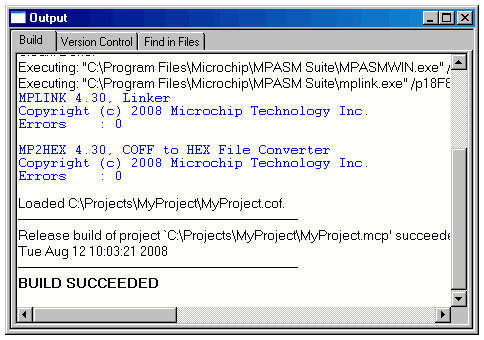
| + | * "Build All": assemble, link and compile your project; the Output window shows the result of the build process. | ||
| + | * "Program Target Device": program the microcontroller with your code; the Output window shows the result of this operation. | ||
| + | |||
| + | [[Image:Output Window.jpg]] | ||
| + | |||
| + | * "Run": after you had build your project and programmed the microcontrolle, now you can run your application on PIC Microcontroller! | ||
| + | * "Halt": halt program execution: the line of code where the application halted will be indicated by the solid green arrow. | ||
| + | * "Reset": reset microcontroller. | ||
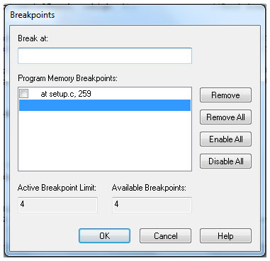
| + | * "BreakPoints": Open the Breakpoint dialog window allowing to set or remove multiple breakpoints. | ||
| + | |||
| + | [[Image:Breakpoints Window.jpg]] | ||
| + | |||
| + | Once you will have create your project, builded it and programmed the microcontroller, in order to see if the code is operating as intended it's possible | ||
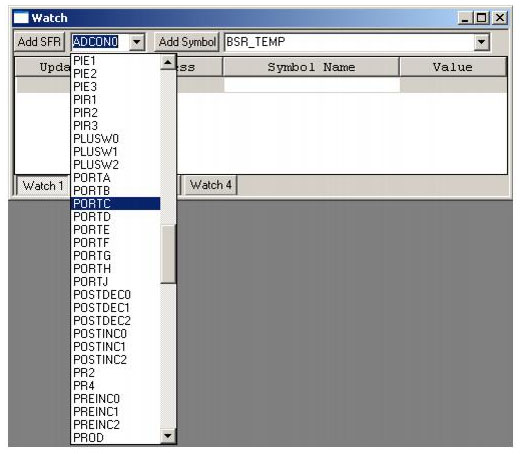
| + | to watch the values being written to microcontroller registers. Select View>Watch to bring up an empty Watch window. There are two pull downs on the top of | ||
| + | the Watch window. The one on the left labeled "Add SFR" can be used to add a phisical microcontroller register into the watch. Select a register from the | ||
| + | list and then click Add SFR to add it to the window. The pull down on the right, allows symbols to be added from the program. Use this pull down to add your | ||
| + | software variable into the Watch window. Select a variable from the list and then click Add Symbol to add it to the window. | ||
| + | The Watch window should now show the address, name and value of the registers you have added. | ||
| + | |||
| + | [[Image:Watch Window.jpg]] | ||
| + | |||
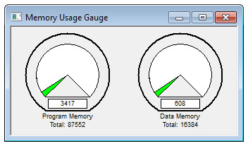
| + | It's possible to control microcontroller memory usage through the "Memory Usage Gauge". You can find it selecting “Memory Usage Gauge” in "View" menu. | ||
| + | Don’t be alarmed! Even though you wrote only few lines of code and the amount of program memory used appears to already be up to 300+ bytes, this is not | ||
| + | an indication of any inherent inefficiency of the C language. There is a minimum block of code that is always generated (for our convenience) by the | ||
| + | C30 compiler. This is the initialization code (c0). | ||
| + | |||
| + | [[Image:Memory Usage Gauge.jpg]] | ||
| + | |||
| + | |||
| + | === Create a new project === | ||
Then, let’s follow the “New Project Set-up” checklist to create a new project with the MPLAB IDE: | Then, let’s follow the “New Project Set-up” checklist to create a new project with the MPLAB IDE: | ||
| Line 143: | Line 198: | ||
* Select “Project->Save” to save the project. | * Select “Project->Save” to save the project. | ||
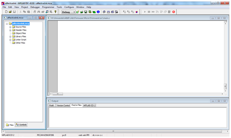
| − | + | You should have a screenshot similar to this one: | |
| − | + | [[Image:MPLAB1.jpg]] | |
| + | On the left you have the files list included in your project. Clicking on a folder you can add files (that you have just created with a simple text editor) | ||
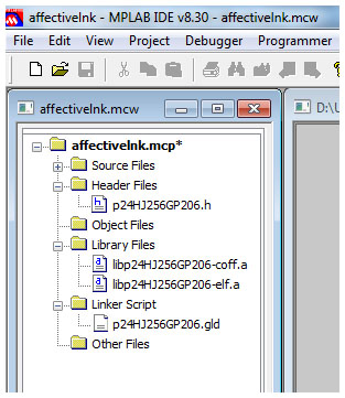
| + | or folder to your project. In "Source Files" folder you must put all ".c" files, while "Header Files" folder is for ".h" files. In this folder you must add | ||
| + | the ".h" file corresponding to your microcontroller: for example, if you use a PIC24HJ256GP206 microcontroller, you will add the "p24hj256gp206.h" | ||
| + | file. These files are located in "C:\Program Files\Microchip\MPLAB C30\support\h\". In "Library Files" folder you have to add the library file corresponding | ||
| + | to your device. As before, if your device is a PIC24HJ256GP206, you will add "libp24HJ256GP206-coff.a" and "libp24HJ256GP206-elf.a" files. These files are | ||
| + | located in "C:\Program Files\Microchip\MPLAB C30\lib\". In the "Linker Script" folder you must add ".gld" file corresponding to your microcontroller. | ||
| + | For PIC24HJ256GP206 the file is "p24HJ256GP206.gld", located in "C:\Program Files\Microchip\MPLAB C30\support\gld\". | ||
| + | On the right top of the screen there is the editor window and on the bottom the output reports window, where you can see if there are some errors building | ||
| + | the code, errors in programmer/debugger connection and all other messages from MPLAB IDE. | ||
| − | + | [[Image:MPLAB2.jpg]] | |
| + | |||
| + | === Write the program === | ||
| + | |||
| + | Our first line of code is going to be: | ||
| + | |||
| + | #include <p24hj256gp206.h> | ||
| + | |||
| + | Note that 24hj256gp206 is the microcontroller used in this example. You must replace it with your own microcontroller model: files are located in | ||
| + | "C:\Program Files\Microchip\MPLAB C30\support\h\". | ||
This is a pseudo-instruction for the preprocessor telling the compiler to read the content of a device-specifi c file before proceeding any further. | This is a pseudo-instruction for the preprocessor telling the compiler to read the content of a device-specifi c file before proceeding any further. | ||
| Line 161: | Line 234: | ||
} | } | ||
| + | |||
| + | This is a complete, although still empty and pretty useless, C-language program. In between those two curly brackets is where to put the instructions of | ||
| + | your embedded-control application. | ||
The main() function is the place where the microcontroller (program counter) will go first at power-up or after each subsequent reset. | The main() function is the place where the microcontroller (program counter) will go first at power-up or after each subsequent reset. | ||
| Line 166: | Line 242: | ||
This is known as the c0 code. The c0 code will perform basic housekeeping chores, including the initialization of the microcontroller stack, among other | This is known as the c0 code. The c0 code will perform basic housekeeping chores, including the initialization of the microcontroller stack, among other | ||
things. | things. | ||
| + | |||
| + | NOTES FOR C EXPERTS: | ||
| + | Standard C library functions (like "printf", for example) are readily available with the MPLAB C30 compiler. But we are | ||
| + | targeting embedded-control applications and we are not writing code for multigigabyte workstations. Get used to | ||
| + | manipulating low-level hardware peripherals inside the PIC24 microcontrollers. A single call to a library function, like | ||
| + | printf, could have added several kilobytes of code to your executable. Don’t assume a serial port and a terminal or a | ||
| + | text display will always be available to you. Instead, develop a sensibility for the “weight” of each function and | ||
| + | library you use in light of the limited resources available in the embedded-design world. | ||
Latest revision as of 09:54, 10 November 2009
!!!___WORK_IN_PROGRESS___!!!
NOTE:
This is not a replacement for the microcontroller datasheet, reference manual and programmer’s manual published by Microchip
Technology. It is also not a replacement for the MPLAB C30 compiler user’s guide, and all the libraries and related software
tools offered by Microchip. Should you notice a conflict between this document and the official documentation, ALWAYS refer
to the latter.
Contents
Part 1: Introduction
Chosing a PIC(TM) Microcontroller
The first step to chose a microcontroller is to focus on hardware/software needs:
- Board power supply is 3V or 5V (or other)?
- Power saving is crucial? You need a Ultra-Micro-Low-Nanowatt-Power microcontroller?
- Application need a little, low cost microcontroller (8bit MCU), a bigger, high performance 16bit MCU or an exagerated 32bit microcontroller?
- What kind and how many peripherics are needed in your application? ADC, UART, Timers, PWM Channels, stackable Interrupts, SPI, I2C, Can Bus, Ethernet, USB... Yes, it's not a joke! High Performance PIC Microcontroller can have one or more USB and/or Ethernet port, you can implement usb mass storage or TCP-IP functions.
- Available memory space: you need an extra large memory because you just know your firmare will be extra long?
Once you have answered some of these questions you can use Microchip Advanced Parts Selector (MAPS(TM)) to find only microcontrollers that satisfy your requirements. MAPS is available on-line or for download directly from Microchip web site (http://www.microchip.com).
Software tools
Let’s verify you have all the necessary equipments, ready and installed (latest version available for download from Microchip web site at http://www.microchip.com):
- PIC MCU Datasheet;
- MPLAB IDE(TM), free Integrated Development Environment;
- MPLAB C30(TM), C compiler (demo or free student version).
Part 2: Basic hardware
Besides a PC, because of we intend "make" something and not only talk about it, we need some hardware tools:
- PIC MCU programmer-debugger (in Ai&R Lab Lambrate you can find some Microchip ICD2(TM) programmer-debugger, some adapter boards with ZIF socket and some self-made programming cables);
- PIC MCU demoboard or your board with power supply, PIC Microconroller, oscillator, MCLR circuitry and some input-output hardware.
If you are watching to buy an own programmer/debugger, Microchip PIC-KIT could be the right choise due to it's little dimensions, low price and good performances. For detailed information, including PIC microcontroller supported list, visit microchip web site.
Oscillator
The system clock (FOSC) source can be provided by a different number of options, depending by microcontroller family (low power, low cost microcontroller allow less options choise than high power, high cost MCU).Generally options can be divided in:
- Internal Oscillator (in general an internal RC network);
- External Oscillator (external clock source, external crystal or ceramic resonator operation and external RC network).
In addition, oscillator system can includes on-chip Phase-Locked Loop (PLL) to boost internal operating frequency, on-the-fly clock switching between various clock sources and Fail-Safe Clock Monitor (FSCM) that detects clock failure and permits safe application recovery or shutdown. This means, for example, that with a PIC24H series microcontoller, you can use a 10Mhz external crystal resonator for clock source, but configuring internal PLL circuitry through dedicated registers, you can obtain a 80Mhz internal clock frequency, achieving 40MIPS core operation speed (PIC24H need two clock cycles to execute a single instruction).
MCLR circuit
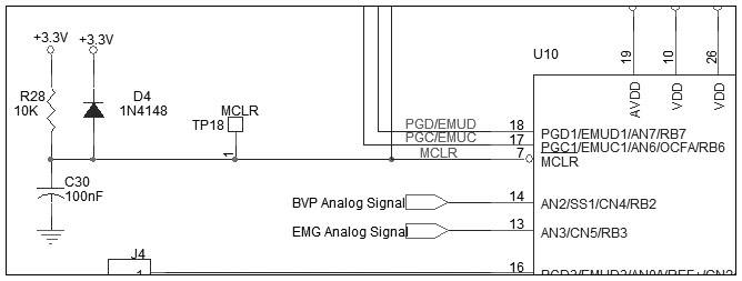
PIC Microcontroller has a number of reset sources and controls (POR: Power-on Reset; BOR: Brown-out Reset; MCLR: Master Clear Pin Reset; WDTO: Watchdog Timer Reset).The external reset is generated by driving the MCLR pin low. The MCLR pin is a Schmitt trigger input with an additional glitch filter. Reset pulses that are longer than the minimum pulse width generates a Reset (see datasheet). The External Reset (MCLR) Pin (EXTR) bit in the Reset Control (RCON) register is set to indicate the MCLR Reset.If your system has an external supervisory circuits that generate reset signals to Reset multiple devices in the system, this external Reset signal can be directly connected to the MCLR pin to reset the device when the rest of system is Reset. When using the internal power supervisory circuit to Reset the device, the external reset pin (MCLR) should be tied directly or resistively to VDD. In this case, the MCLR pin is not used to generate a Reset. The external reset pin (MCLR) does not have an internal pull-up and must not be left unconnected. A typical power-on reset circuit is:
Programming/Debugging interface
ICSP(TM) (In-Circuit Serial Programming(TM)) mode is a special programming protocol that allows you to read and write to PIC Microcontroller and is the most direct method used to program the device.The ICSP capability is Microchip’s proprietary process for microcontroller programming in the target application. The ICSP interface uses two pins as its core. The programming data pin (PGD) functions as both an input and an output, allowing programming data to be read in and device information to be read out on command. The programming clock pin (PGC) clocks in data and controls the overall process.
Serial programming allows customers to manufacture boards with unprogrammed devices and then to program the digital signal controller just before shipping the product. Serial programming also allows the most recent firmware or a custom firmware to be programmed.
Depending from used Microcontroller it's possible to have one or more programming ports. PIC24HJ256JP206, for example, has three pairs of programming clock/data pins:
- PGC1/EMUC1 and PGD1/EMUD1
- PGC2/EMUC2 and PGD2/EMUD2
- PGC3/EMUC3 and PGD3/EMUD3
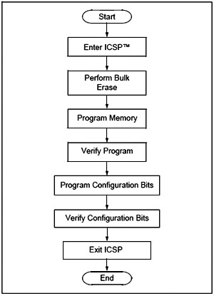
Used programming port must be specified in MPLAB IDE selecting "Configuration Bits..." in "Configure" menu. The High-Level ICSP Programming Flow is:
When the MPLAB(TM) ICD 2 or another in-circuit emulator is selected as a debugger,the in-circuit debugging functionality is enabled. This function allows simple debugging when used with MPLAB IDE. The debugging functionality is controlled through the EMUCx (emulation/debug clock) and EMUDx (emulation/debug data) pin functions. To use the in-circuit debugger function of the device, the design must implement ICSP connections to MCLR, VDD, VSS, PGCx/EMCx and PGDx/EMUDx pin pairs. In addition, when the feature is enabled, some of the resources are not available for general use.
Programmer Connection
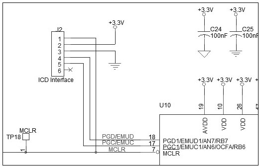
ICD 2 programmer/debugger has a RJ12 6 pin output connector while PIC-KIT has a more comfortable 6 pin female strip headers. The simplest way to interface programmer/debugger with microcontroller is to solder a 6 pin male strip headers to your board connetting PGCX, PGDX, MCLR, VDD and VSS pins, as in figure:
Connecting pins in the same order as in figure you can either connect directly PIC-KIT to your board, or use an RJ12->female_strip_headers adapter cable to connect ICD 2 to target device. You can find two of that selfmade cabe in AI&R Lab, or you can build your own one using an RJ12 connector, a piece of 6 core cable (you can use also a piece of 8 core ethernet cable), a 6 pin female strip headers and a bit of talent!
Part 3: PIC MCU programming
MPLAB IDE settings
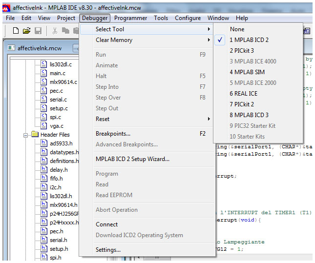
Select in "Debugger" menu the programmer/debugger device you have to use (probably "1 MPLAB ICD 2", if you are working on AI&R Lab...)
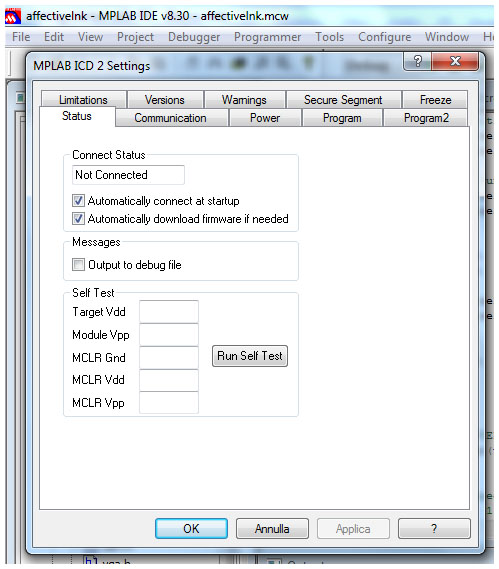
To verify if programmer/debugger is connected to your Pc, to PIC microcontroller and is ready to operate select "Settings" in "Debug" menu and than pres "Run Self Test" in the just opened window:
In this window you can also check the correct target power supply ("Power" submenu) and change PC-Programmer/debugger communication port ("Communications" submenu).
Let's talk about usefull functions on tool bar:
- "Save File": save only the file you are working on.
- "Find in Files": find a word in all files included in the project.
- "Build Configuration": to set up language tools for debug, select "Debug"; when your code is debugged and you are ready to release it (program the finished
code into a device), select "Release".
- "Open Project": open a just created project.
- "Save Workspace": save all files in your project and workspace (windows placement on the screen).
- "Build All": assemble, link and compile your project; the Output window shows the result of the build process.
- "Program Target Device": program the microcontroller with your code; the Output window shows the result of this operation.
- "Run": after you had build your project and programmed the microcontrolle, now you can run your application on PIC Microcontroller!
- "Halt": halt program execution: the line of code where the application halted will be indicated by the solid green arrow.
- "Reset": reset microcontroller.
- "BreakPoints": Open the Breakpoint dialog window allowing to set or remove multiple breakpoints.
Once you will have create your project, builded it and programmed the microcontroller, in order to see if the code is operating as intended it's possible to watch the values being written to microcontroller registers. Select View>Watch to bring up an empty Watch window. There are two pull downs on the top of the Watch window. The one on the left labeled "Add SFR" can be used to add a phisical microcontroller register into the watch. Select a register from the list and then click Add SFR to add it to the window. The pull down on the right, allows symbols to be added from the program. Use this pull down to add your software variable into the Watch window. Select a variable from the list and then click Add Symbol to add it to the window. The Watch window should now show the address, name and value of the registers you have added.
It's possible to control microcontroller memory usage through the "Memory Usage Gauge". You can find it selecting “Memory Usage Gauge” in "View" menu. Don’t be alarmed! Even though you wrote only few lines of code and the amount of program memory used appears to already be up to 300+ bytes, this is not an indication of any inherent inefficiency of the C language. There is a minimum block of code that is always generated (for our convenience) by the C30 compiler. This is the initialization code (c0).
Create a new project
Then, let’s follow the “New Project Set-up” checklist to create a new project with the MPLAB IDE:
- Select “Project->Project Wizard” to activate the new project wizard, which will guide us automatically through the following steps…
- Select the correct PIC device, and click Next.
- Select the MPLAB C30 Compiler Suite and click Next.
- Create a new folder and name it “FolderName”; name the project “ProjectName” and click Next.
- Click Next to the following dialog (box—there is no need to copy any source files from any previous projects or directories.
- Click on Finish to complete the Wizard set-up.
Open a new editor window.
- Select “File->Save As”, to save the file as: “FileName.c”.
- Select “Project->Save” to save the project.
You should have a screenshot similar to this one:
On the left you have the files list included in your project. Clicking on a folder you can add files (that you have just created with a simple text editor) or folder to your project. In "Source Files" folder you must put all ".c" files, while "Header Files" folder is for ".h" files. In this folder you must add the ".h" file corresponding to your microcontroller: for example, if you use a PIC24HJ256GP206 microcontroller, you will add the "p24hj256gp206.h" file. These files are located in "C:\Program Files\Microchip\MPLAB C30\support\h\". In "Library Files" folder you have to add the library file corresponding to your device. As before, if your device is a PIC24HJ256GP206, you will add "libp24HJ256GP206-coff.a" and "libp24HJ256GP206-elf.a" files. These files are located in "C:\Program Files\Microchip\MPLAB C30\lib\". In the "Linker Script" folder you must add ".gld" file corresponding to your microcontroller. For PIC24HJ256GP206 the file is "p24HJ256GP206.gld", located in "C:\Program Files\Microchip\MPLAB C30\support\gld\". On the right top of the screen there is the editor window and on the bottom the output reports window, where you can see if there are some errors building the code, errors in programmer/debugger connection and all other messages from MPLAB IDE.
Write the program
Our first line of code is going to be:
#include <p24hj256gp206.h>
Note that 24hj256gp206 is the microcontroller used in this example. You must replace it with your own microcontroller model: files are located in "C:\Program Files\Microchip\MPLAB C30\support\h\".
This is a pseudo-instruction for the preprocessor telling the compiler to read the content of a device-specifi c file before proceeding any further. The content of the device-specifi c “.h” file chosen is a long list of the names (and sizes) of all the internal special-function registers (SFRs) of the chosen PIC model: those names reflect exactly those being used in the device datasheet. Let’s add a couple more lines that will introduce you to the main() function:
main()
{

}
This is a complete, although still empty and pretty useless, C-language program. In between those two curly brackets is where to put the instructions of your embedded-control application.
The main() function is the place where the microcontroller (program counter) will go first at power-up or after each subsequent reset. Before entering the main() function, the microcontroller will execute a short initialization code segment automatically inserted by the linker. This is known as the c0 code. The c0 code will perform basic housekeeping chores, including the initialization of the microcontroller stack, among other things.
NOTES FOR C EXPERTS:
Standard C library functions (like "printf", for example) are readily available with the MPLAB C30 compiler. But we are
targeting embedded-control applications and we are not writing code for multigigabyte workstations. Get used to
manipulating low-level hardware peripherals inside the PIC24 microcontrollers. A single call to a library function, like
printf, could have added several kilobytes of code to your executable. Don’t assume a serial port and a terminal or a
text display will always be available to you. Instead, develop a sensibility for the “weight” of each  function and
library you use in light of the limited resources available in the embedded-design world.
