Difference between revisions of "TiltOne"
(→Electrical project) |
m (→Classical controllers) |
||
| (33 intermediate revisions by 3 users not shown) | |||
| Line 1: | Line 1: | ||
{{Project | {{Project | ||
|title=TiltOne | |title=TiltOne | ||
| − | |image= | + | |image=Tiltone_3.jpg |
|short_descr=Balancing robot | |short_descr=Balancing robot | ||
|coordinator=AndreaBonarini; | |coordinator=AndreaBonarini; | ||
|tutor=MartinoMigliavacca; | |tutor=MartinoMigliavacca; | ||
| + | |collaborator=GiulioFontana; | ||
| + | |students=AndreaGalbiati; | ||
|resarea=Robotics | |resarea=Robotics | ||
|restopic=Robot development | |restopic=Robot development | ||
| − | |start= | + | |start=2010/09/20 |
| − | |end= | + | |end=2011/02/20 |
|status=Active | |status=Active | ||
| − | |level= | + | |level=Bs |
|type=Thesis | |type=Thesis | ||
}} | }} | ||
| − | |||
| − | + | TiltOne is a two-wheels balancing robot, designed for service applications which need a tall robot (it is 120cm tall) keeping a small footprint, e.g., home assistance, office bellboy, advertising purposes, robotic waiter, assistant to move heavy objects. | |
| + | |||
| + | TiltOne has only two wheels, which are actuated to keep itself in equilibrium. It is designed to be able to carry a quite high payload (up to 50kg) travelling at speeds of about 1.5m/s. | ||
| + | |||
| + | The robot is controlled by a microcontroller that runs two different balance algorithms: the first implements classical control laws, analytically tuned, while the other is obtained by machine learning techniques, where the robot learns how to keep the equilibrium. | ||
== Mechanical project == | == Mechanical project == | ||
| Line 53: | Line 58: | ||
==== Robot controller ==== | ==== Robot controller ==== | ||
| − | The robot is controlled by a board built around a STM32 ARM7 Cortex M3 microcontroller | + | The robot is controlled by a board built around a STM32 ARM7 Cortex M3 microcontroller by ST Microelectronics. |
| − | [[Image:tiltone_board_blocks.png]] | + | [[Image:tiltone_board_blocks.png|720px]] |
The microcontroller acquires sensors data, apply a control law and commits a command to the motors. The software running on the ARM is real-time oriented, having periodic tasks constantly running at different frequencies and some interrupt-driven events that can modify the program flow. | The microcontroller acquires sensors data, apply a control law and commits a command to the motors. The software running on the ARM is real-time oriented, having periodic tasks constantly running at different frequencies and some interrupt-driven events that can modify the program flow. | ||
| Line 61: | Line 66: | ||
== Stability and motion control == | == Stability and motion control == | ||
| + | |||
| + | We have implemented different algorithms to control the stability of the robot and it's movements. Some of them are based on classical control laws, while others exploit machine learning techniques. | ||
==== Classical controllers ==== | ==== Classical controllers ==== | ||
| + | |||
| + | A classical PID controller has been developed for stability control. A simple P-I controller keeps the robot in vertical position, but it is not robust and can't follow a speed o position setpoint. | ||
| + | |||
| + | A better controller was introduced to enhance robot reaction to external disturbances and to follow speed setpoints. A simplified schema of the controller is presented in the following figure. | ||
| + | |||
| + | [[Image:tiltone_pid_controller.png|720px]] | ||
| + | |||
| + | * C1 and C2 are the tilt controllers. C1 is a PI, obtained by root locus analysis of the system, that makes the system stable. While C2 is a PID, obtained studying the bode plot of the system, that improves stability performance. | ||
| + | * C3 is the speed controller that acts changing the angle setpoint of the tilt controllers (nested PID approach) | ||
==== Reinforcement Learning approach ==== | ==== Reinforcement Learning approach ==== | ||
| − | + | Machine learning techniques have been exploited to keep the robot stable. The approach we used is based on offline FQI reinforcement learning algorithms, and some continuous-time variants to smooth robot movements. | |
| + | Basically, the robot is able to learn automatically a control policy (a function, or a lookup table, that maps the state variables to a control action) by an analysis of data collected with random motor commands. The learning process consists in three steps: | ||
| + | * the robot is controlled by random commands, so it shakes for a while (usually 1-2 seconds) and then falls down | ||
| + | * collected data is analyzed with a FQI policy search algorithm and a policy is obtained | ||
| + | * the policy is tested on the robot, and more data is collected to recursively apply the algorithm | ||
| + | The figure on the left shows starting data collected by applying random commands, while on the right the obtained policy to keep the robot vertical is reported. | ||
| + | |||
| + | [[Image:Tiltone_rl_space.png|420px]] | ||
| + | [[Image:Rl_policy_angle.png|420px]] | ||
| + | |||
| + | == Resources == | ||
| + | |||
| + | ==== Thesis ==== | ||
| + | |||
| + | * Master thesis by Martino Migliavacca (in Italian): "Progetto e realizzazione di una base robotica bilanciante su ruote" (Design and development of a two-wheel balancing platform). [[Media:TiltOne_tesi_Migliavacca.pdf]] | ||
| + | |||
| + | * Project presentation slides by Martino Migliavacca (in Italian). [[Media:Tiltone_Presentation_Migliavacca.pdf]] | ||
| + | |||
| + | * First level thesis by Andrea Galbiati (in Italian): "Progettazione e realizzazione del controllo di una base robotica bilanciante su ruote" (Control design and implementation for a two-wheel balancing platform). [[Media:TiltOne_tesi_Galbiati.pdf]] | ||
| + | |||
| + | ==== YouTube videos ==== | ||
| + | * tiltOne's first steps | ||
{{#ev:youtube|4FrA73Cxljs}} | {{#ev:youtube|4FrA73Cxljs}} | ||
| − | == External links == | + | |
| + | * tiltOne's Ad | ||
| + | {{#ev:youtube|NvGMq4Qig7M}} | ||
| + | |||
| + | |||
| + | *tiltOne naughty waiter | ||
| + | {{#ev:youtube|JLQ06vOvRsU}} | ||
| + | |||
| + | |||
| + | * tiltOne is stable | ||
| + | {{#ev:youtube|VASMfKkpK6c}} | ||
| + | |||
| + | |||
| + | * Remote control with joypad | ||
| + | {{#ev:youtube|V0U4vNpM_z8}} | ||
| + | |||
| + | |||
| + | <!--* tiltOne at Robotica 2011 | ||
| + | {{#ev:youtube|jux6vbNTdcQ}}--> | ||
| + | |||
| + | ==== External links ==== | ||
| + | - Inverted pendulum on Wikipedia | ||
http://en.wikipedia.org/wiki/Inverted_pendulum | http://en.wikipedia.org/wiki/Inverted_pendulum | ||
| + | |||
| + | - Matlab tutorial about controlling an inverted pendulum (Modeling, PID, LQR, etc) | ||
| + | http://www.engin.umich.edu/group/ctm/examples/pend/invSS.html#lqr | ||
Latest revision as of 17:05, 18 September 2014
TiltOne
| |
| Short Description: | Balancing robot |
| Coordinator: | AndreaBonarini (andrea.bonarini@polimi.it) |
| Tutor: | MartinoMigliavacca (migliavacca@elet.polimi.it) |
| Collaborator: | GiulioFontana (giulio.fontana@polimi.it) |
| Students: | AndreaGalbiati (andrea6.galbiati@mail.polimi.it) |
| Research Area: | Robotics |
| Research Topic: | Robot development |
| Start: | 2010/09/20 |
| End: | 2011/02/20 |
| Status: | Active |
| Level: | Bs |
| Type: | Thesis |
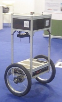
TiltOne is a two-wheels balancing robot, designed for service applications which need a tall robot (it is 120cm tall) keeping a small footprint, e.g., home assistance, office bellboy, advertising purposes, robotic waiter, assistant to move heavy objects.
TiltOne has only two wheels, which are actuated to keep itself in equilibrium. It is designed to be able to carry a quite high payload (up to 50kg) travelling at speeds of about 1.5m/s.
The robot is controlled by a microcontroller that runs two different balance algorithms: the first implements classical control laws, analytically tuned, while the other is obtained by machine learning techniques, where the robot learns how to keep the equilibrium.
Contents
Mechanical project
Frame
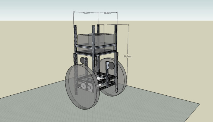
As the robot needs to keep the wheel axis just under it's center of mass to mantain the unstable equilibrium point, it's inertia should be high in the upper part of the frame and low at the wheel level, allowing the base to move while the center of mass holds - ideally - it's position. For this reason the batteries, that are the heavier component of the robot, are mounted at the top of the frame.
A preview of the robot structure was realized using Google Sketchup 6, giving a first idea about it's dimensions and components placement Media:Tiltone_2_-_completo.zip.
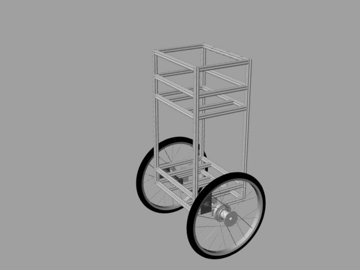
The robot frame is built using standard aluminium profiles (http://www.item.info) to allow future modifications and provide simple solutions to attach auxiliar devices.
Wheels and transmission
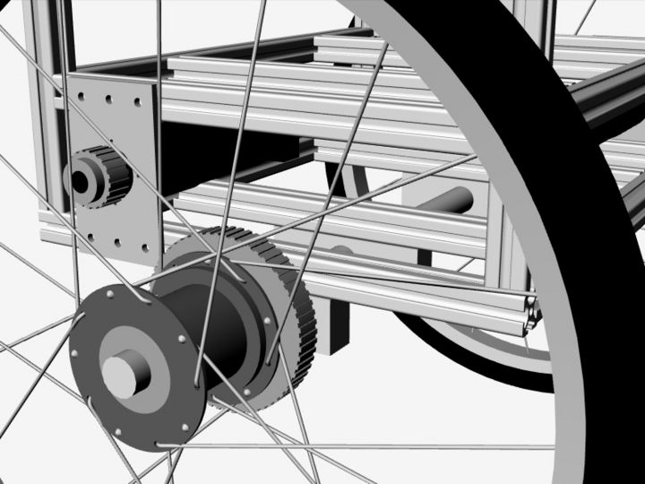
The mechanical project was then realized using Rinoceros 4.0 CAD. Apart from the robot frame, particular attention was dedicated to the design of the transmission and the wheel hub, that allow to use standard cross-bike wheels Media:Tiltone_3_Rhinoceros.zip.
The robot is actuated by two high-power electrical DC motor from Maxon Motor (www.maxonmotor.com) that provide torque to the wheels via a belt drive system.
Electrical project
Sensors
What the robot needs to control it's behavior are it's angle and angular velocity with respect to the direction of the gravitational force and the current speed of the wheels.
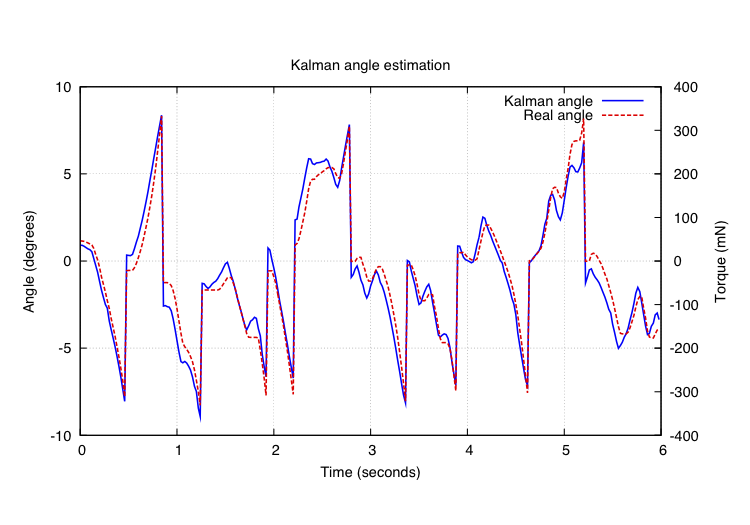
To acquire the robot angle and the angular velocity two sensors are used: an accelerometer (LIS344ALH by ST Microelectronics), that gives the components of the gravitational force along the vertical and horizontal axes of the frame, and a gyroscope (ADXRS150 from Analog Devices), that can directly measure the angular velocity with respect to the wheel axis. In order to reduce the influence of robot's movements sensed by the accelerometer, and to avoid the drift of the gyroscope readings, these two measurements are fused with a Kalman filter. The output of the filter is an estimate of robot's angle and angular velocity that tracks very well the real data.
Wheel's speed is obtained by two optical encoders (HEDS-5540 from Agilent) directly attached to the motor rotors, that allow to evaluate the rotor speed and to drive the motors with a closed loop controller.
Robot controller
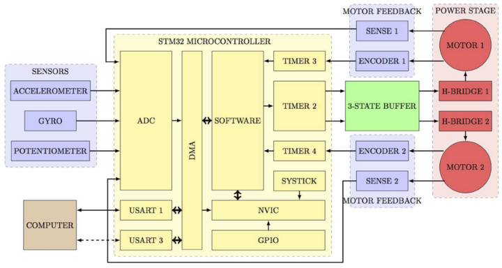
The robot is controlled by a board built around a STM32 ARM7 Cortex M3 microcontroller by ST Microelectronics.
The microcontroller acquires sensors data, apply a control law and commits a command to the motors. The software running on the ARM is real-time oriented, having periodic tasks constantly running at different frequencies and some interrupt-driven events that can modify the program flow. The board provides also a serial interface to an external PC used to program the microcontroller and a wireless Zigbee module allowing to communicate with the robot
Stability and motion control
We have implemented different algorithms to control the stability of the robot and it's movements. Some of them are based on classical control laws, while others exploit machine learning techniques.
Classical controllers
A classical PID controller has been developed for stability control. A simple P-I controller keeps the robot in vertical position, but it is not robust and can't follow a speed o position setpoint.
A better controller was introduced to enhance robot reaction to external disturbances and to follow speed setpoints. A simplified schema of the controller is presented in the following figure.
- C1 and C2 are the tilt controllers. C1 is a PI, obtained by root locus analysis of the system, that makes the system stable. While C2 is a PID, obtained studying the bode plot of the system, that improves stability performance.
- C3 is the speed controller that acts changing the angle setpoint of the tilt controllers (nested PID approach)
Reinforcement Learning approach
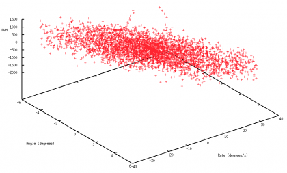
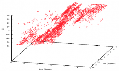
Machine learning techniques have been exploited to keep the robot stable. The approach we used is based on offline FQI reinforcement learning algorithms, and some continuous-time variants to smooth robot movements. Basically, the robot is able to learn automatically a control policy (a function, or a lookup table, that maps the state variables to a control action) by an analysis of data collected with random motor commands. The learning process consists in three steps:
- the robot is controlled by random commands, so it shakes for a while (usually 1-2 seconds) and then falls down
- collected data is analyzed with a FQI policy search algorithm and a policy is obtained
- the policy is tested on the robot, and more data is collected to recursively apply the algorithm
The figure on the left shows starting data collected by applying random commands, while on the right the obtained policy to keep the robot vertical is reported.
Resources
Thesis
- Master thesis by Martino Migliavacca (in Italian): "Progetto e realizzazione di una base robotica bilanciante su ruote" (Design and development of a two-wheel balancing platform). Media:TiltOne_tesi_Migliavacca.pdf
- Project presentation slides by Martino Migliavacca (in Italian). Media:Tiltone_Presentation_Migliavacca.pdf
- First level thesis by Andrea Galbiati (in Italian): "Progettazione e realizzazione del controllo di una base robotica bilanciante su ruote" (Control design and implementation for a two-wheel balancing platform). Media:TiltOne_tesi_Galbiati.pdf
YouTube videos
- tiltOne's first steps
- tiltOne's Ad
- tiltOne naughty waiter
- tiltOne is stable
- Remote control with joypad
External links
- Inverted pendulum on Wikipedia http://en.wikipedia.org/wiki/Inverted_pendulum
- Matlab tutorial about controlling an inverted pendulum (Modeling, PID, LQR, etc) http://www.engin.umich.edu/group/ctm/examples/pend/invSS.html#lqr
