Difference between revisions of "LionHell McMillan II"
| Line 23: | Line 23: | ||
End date: 2015/04/29 | End date: 2015/04/29 | ||
</pre> | </pre> | ||
| + | |||
| + | |||
| + | <h2> <span class="mw-headline" id="state_art">State of the Art</span></h2> | ||
| + | <h3> <span class="mw-headline" id="Wheg">Wheg</span></h3> | ||
| + | |||
| + | The locomotion system is the key element that allows the robot to | ||
| + | interface and explore the surrounding environment and requires a careful choice | ||
| + | that meets the requirements of handling, mechanical simplicity and fluidity | ||
| + | motion, ensuring, in this case, the possibility to move easily | ||
| + | on rough terrain, overcoming obstacles of small and medium | ||
| + | size. | ||
| + | |||
| + | <h4> <span class="mw-headline" id="Definition_Wheg">Definition of the Wheg</span></h4> | ||
| + | |||
| + | [[File:Description wheg.PNG|300px]][[File:Wheg 0 rotazione.PNG|600px]] | ||
| + | |||
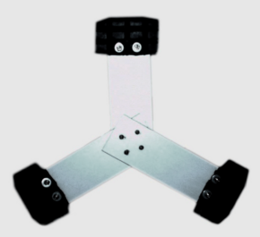
| + | The Wheg are a mechanism of locomotion for robots that combine | ||
| + | simplicity of movement of a wheel with the ability to scale and to overcome | ||
| + | obstacles arising from the use of the legs. The acronym derives | ||
| + | by the combination of words wheel and leg and mechanically it | ||
| + | consists of a central rotary axis and which are connected one or more bars | ||
| + | which perform the function of the legs. | ||
| + | The operation of a Wheg is extremely simple: the three legs are connected to a central axis that rotates | ||
| + | on itself and the point of contact with the ground is made from the end | ||
| + | of the leg. | ||
| + | |||
| + | <h4> <span class="mw-headline" id="_vs_Wheel">Wheg vs Wheel</span></h4> | ||
| + | |||
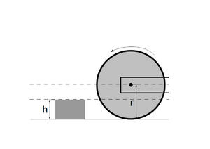
| + | The superiority of Wheg comparison to the use of a simple wheel is easily | ||
| + | demonstrated: | ||
| + | |||
| + | [[File:Ruota1ostacoloPiccolo.png|300px]][[File:Ruota2ostacoloPiccolo.png|300px]][[File:Ruota3ostacoloPiccolo.png|300px]] | ||
| + | |||
| + | <ol> | ||
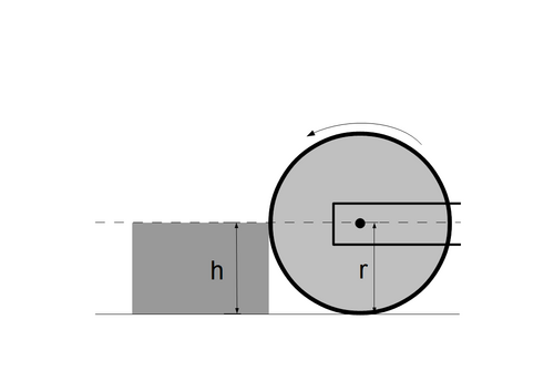
| + | <li> Consider a wheel that is about to face an obstacle placed on the floor, much smaller than the radius | ||
| + | the wheel itself; </li> | ||
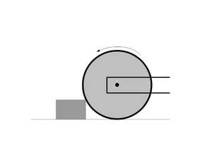
| + | <li> Once the wheel comes into contact with the obstacle, the clutch | ||
| + | that is generated will force the point of contact to remain in the same | ||
| + | position and while the torsion of the wheel will continue to act, the point | ||
| + | contact will function as a pivot. If the power of the engine will be | ||
| + | enough the result will be that the wheel will walk across continuing | ||
| + | in its path; </li> | ||
| + | </ol> | ||
| + | [[File:Ruota1ostacoloGrande.png|500px]] | ||
| + | <ol> | ||
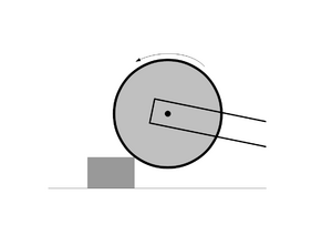
| + | <li>Now consider a similar situation, in which, however, the obstacle that | ||
| + | wheel must be facing the same overall height of its radius (h similar to r). In this case the contact point is on the side of the obstacle, | ||
| + | and not above as in the previous case and the clutch that you should | ||
| + | come and create so that it can be climbed should be such that | ||
| + | allow the robot to move in a vertical manner with respect to the obstacle. | ||
| + | Typically, this situation is not a realistic scenario and the | ||
| + | experiment result will be that the wheel will start to slip on the spot, | ||
| + | continuously changing the point of contact with the obstacle. Due to the fact | ||
| + | the wheel would fail in this scenario, the wheel would fail for all | ||
| + | scenarios where h > r as the contact point will always be on the | ||
| + | side of the obstacle and not above. </li> | ||
| + | </ol> | ||
| + | |||
| + | [[File:Wheg1ostacoloGrande.png|300px]][[File:Wheg1ostacoloGrande.png|300px]][[File:Wheg1ostacoloGrande.png|300px]] | ||
| + | |||
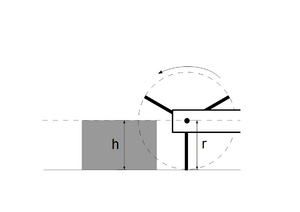
| + | Consider now the previous example, in which h is similar to r, but where in place | ||
| + | of the wheel there is a Wheg three legs (in figures can be | ||
| + | observe the presence of a circle around the Wheg: this circle is purely | ||
| + | illustrative and serves only to relate the size of Wheg | ||
| + | compared to those of the wheel): | ||
| + | <ol> | ||
| + | <li>First, you can see the huge gap that the structure | ||
| + | presents, space that will be used to your advantage: the structure | ||
| + | is in fact able to exploit the empty space, facing the obstacle | ||
| + | from above and not from the side as in the case of the wheel; </li></i> | ||
| + | <li>The force exerted by the engines and the twist of Wheg will do the rest, | ||
| + | allowing the exploitation of the point of contact as a pivot to raise the Wheg frame and overcome the obstacle (you | ||
| + | always remember that the circle only serves to show the trajectory | ||
| + | of the three legs); </li> | ||
| + | </ol> | ||
| + | |||
| + | [[File:Wheg1ostacoloEnorme.png|400px]] | ||
| + | |||
| + | <ol> | ||
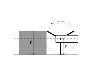
| + | <li>Now consider another example, in | ||
| + | where we have h > r, and in particular the case in which h = 3/2 r (as | ||
| + | there are 3 legs). In this extreme case the Wheg will not be | ||
| + | able to overcome the obstacle: the ability to climb it depends on how the | ||
| + | Wheg is capable of penetrating the profile of the obstacle. You can get | ||
| + | this goal by reducing the angle between the two upper legs, but this | ||
| + | undermine the structure of Wheg making unstable. </li> | ||
| + | </ol> | ||
| + | |||
| + | From this analysis it is possible to highlight the main advantages and disadvantages | ||
| + | of using a Wheg: | ||
| + | <ul> | ||
| + | <li> Pro: the ability to climb obstacles of greater height than those | ||
| + | addressed by a wheel having the same radius; </li> | ||
| + | <li> Pro: the speed of movement of the robot is still high; </li> | ||
| + | <li> Pro: the greater simplicity of construction and control compared to | ||
| + | a leg, which must necessarily be controlled by two or | ||
| + | three actuators; </li> | ||
| + | <li> Cons: The land on which it moves must be rough, in order to | ||
| + | do strength and be able to overcome the obstacle; </li> | ||
| + | <li> Cons: Legs too thin could sink surfaces | ||
| + | soft or non-rigid, such as sand or mud, due to the | ||
| + | reduced contact surface; </li> | ||
| + | <li> Cons: If your legs hit moving parts, such as long grass or cables | ||
| + | very thin, the Wheg could be twisted, latching | ||
| + | and risking damage to the robot in the case where the motors | ||
| + | trying to do too much force to break free. </li> | ||
| + | </ul> | ||
<h2> <span class="mw-headline" id="CM_LionHell_II">Control and Mobility in LionHell II</span></h2> | <h2> <span class="mw-headline" id="CM_LionHell_II">Control and Mobility in LionHell II</span></h2> | ||
| Line 116: | Line 223: | ||
</ul> | </ul> | ||
| − | <h2> <span class="mw-headline" id=" | + | <h2> <span class="mw-headline" id="RC_LionHell_II">Remote Control in LionHell II</span></h2> |
| + | |||
| + | <h3> <span class="mw-headline" id="Remote_controller">Remote controller</span></h3> | ||
| + | |||
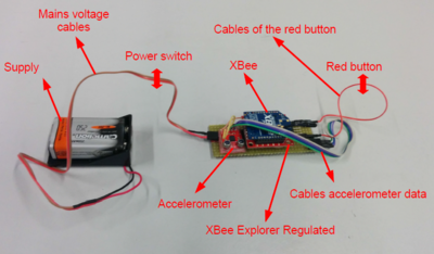
| + | The figure shows the basic components of the remote control (excluding | ||
| + | a button and the switch, which for practical reasons are not shown in | ||
| + | figure, being incorporated into the external structure of the remote control). | ||
| + | The remote control is made up of: | ||
| + | <ul> | ||
| + | <li> a 9 V battery and 250 mAh which is the power; </li> | ||
| + | <li> an XBee Explorer Regulated that deals with the tension adjustment 3.3V, the signal conditioning and the basic activity indicators | ||
| + | and converts the signals from 5V to 3.3V in order to connect the system to any XBee module; </li> | ||
| + | <li> an XBee 4214A which plays the role of transmitting the signals received in input and communicates to the XBee installed on the body of LionHell II; </li> | ||
| + | <li> a three-axis analog accelerometer ADXL335, with card detection +/- 3g devoid of voltage regulator (the input voltage must be between 1.8V and 3.6V dc); </li> | ||
| + | <li> a circuit breaker switch that plays the role of power switch ON and OFF; </li> | ||
| + | <li> a red button unstable normally open, which allows the use the remote control while pressing. </li> | ||
| + | </ul> | ||
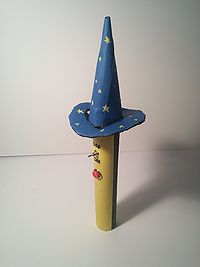
| + | The movement of LionHell II is via the inclination of the remote control(pointing the tip of the magician's hat forward and with the red button | ||
| + | upwards the robot is stationary, while raising or lowering the hat you can make it go forwards or backwards, and tilting | ||
| + | the remote control to the right or the left, the robot rotates to the right or left, respectively), which detects a change of axes X and Y by means | ||
| + | the accelerometer. The values are then passed to the XBee installed on remote control, which sends them directly to the XBee on LionHell II. | ||
| + | |||
| + | [[File:Remote controller 1.jpg|200px]][[File:Remote controller components.PNG|400px]] | ||
| + | |||
| + | <h3> <span class="mw-headline" id="XBee_LionHell">XBee of LionHell II</span></h3> | ||
| + | |||
| + | The goal of the XBee is to receive data from the remote control and send the data so | ||
| + | received to the control board LionHell II, with the result that the control board doesn't notice | ||
| + | even the existence of the XBee, as if it is reading data directly from the | ||
| + | remote controller. | ||
| + | |||
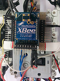
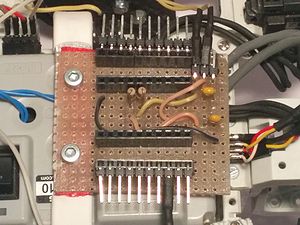
| + | The figures show the XBee 4214A used LionHell II, mounted directly | ||
| + | above the control board CM-510, at the center of the body of the robot, | ||
| + | and the the components underlying the XBee. How it is possible to | ||
| + | observe, are present (for each of the two digital inputs) a resistance | ||
| + | and a capacitor: the reason is easily explained. | ||
| + | The data transmitted from the XBee of the remote controller to the XBee of LionHell II are in analog form, but the inputs | ||
| + | control board does not require a digital type wave | ||
| + | square (obtainable via an inverting gate NOT, a Schmitt trigger, | ||
| + | a capacitor and a resistor) but through a filter of low-pass type (which | ||
| + | only requires the use of an RC circuit, based precisely on the use | ||
| + | of a resistor and a dynamic element, the capacitor). | ||
| + | |||
| + | [[File:XBee LionHell II.jpg|200px]] | ||
| + | [[File:XBee below LionHell II.jpg|300px]] | ||
| + | |||
| + | <h3> <span class="mw-headline" id="firmware_movement">Changes to the firmware</span></h3> | ||
| + | |||
| + | Once the signal is started by the remote, it's been installed on the XBee | ||
| + | on LionHell II and has been suitably modified to return | ||
| + | the original values read initially by the accelerometer of the remote control, | ||
| + | it is the turn of the control board CM-510. | ||
| + | The board acts as if it reads the values directly from the accelerometer, | ||
| + | doesn't even notice the existence of all the intermediate components, and | ||
| + | discriminates on the basis of these values the actions to be taken. Below there is | ||
| + | code of LionHell II reading the accelerometer values: | ||
| + | |||
| + | <pre> | ||
| + | // Read Remote Controller via XBee using Virtual Wires | ||
| + | { | ||
| + | resultX = adc_start( 4 ); | ||
| + | resultY = adc_start( 3 ); | ||
| + | bRemoteButton = (PINE & BTN_RIGHT) ; | ||
| + | // printf( "\r \n resultX resultY button: %u %u %d " ,resultX, resultY , bRemoteButton ) ; | ||
| + | // BUTTON | ||
| + | if ( bRemoteButton ) | ||
| + | { | ||
| + | walking = true ; | ||
| + | } | ||
| + | else | ||
| + | { | ||
| + | walking = false ; | ||
| + | } | ||
| + | //X | ||
| + | if ( resultX > 340 ) | ||
| + | { | ||
| + | turnL = 0 ; turnR=0; // Go Fwd | ||
| + | } else | ||
| + | if ( resultX < 300 ) | ||
| + | { | ||
| + | turnL = 1 ; turnR=1; // Go Bwd | ||
| + | } | ||
| + | //Y | ||
| + | if ( resultY > 340 ) | ||
| + | { | ||
| + | turnR = 1 ; turnL=0; // Turn Right | ||
| + | } else | ||
| + | if ( resultY < 300 ) | ||
| + | { | ||
| + | turnL = 1 ; turnR=0; // Turn Left | ||
| + | } | ||
| + | } | ||
| + | </pre> | ||
| + | |||
| + | The code shows a first reading of the values X and Y of the accelerometer, | ||
| + | saved in variables resultX and resultY, later | ||
| + | is read the value of the red button by the variable bRemoteButton. | ||
| + | In the case where the red button is pressed then the variable walking | ||
| + | is set to true and based on the values of resultX and | ||
| + | resultY is chosen the direction to take. | ||
| + | The following code shows the behaviour of LionHell | ||
| + | II after the reception of the signals of the accelerometer and after that has been chosen | ||
| + | the action to be performed: | ||
| + | |||
| + | <pre> | ||
| + | //Walking Actions | ||
| + | if ( walking==1){ | ||
| + | if ( turnL && turnR) { | ||
| + | int i ; | ||
| + | for ( i =0; i <3; i++){//Go Backward | ||
| + | dxl_write_word ( whegs_sx [ i ] , | ||
| + | P_MOVING_SPEED_L, 1624 ) ; | ||
| + | dxl_write_word ( whegs_dx [ i ] , | ||
| + | P_MOVING_SPEED_L, 600 ) ; | ||
| + | } | ||
| + | } else | ||
| + | if ( turnL ) {//Turn Left | ||
| + | int i ; | ||
| + | for ( i =0; i <3; i++){ | ||
| + | dxl_write_word ( whegs_sx [ i ] , | ||
| + | P_MOVING_SPEED_L, 1624 ) ; | ||
| + | dxl_write_word ( whegs_dx [ i ] , | ||
| + | P_MOVING_SPEED_L, 1624 ) ; | ||
| + | // dxl_wri te_word ( whegs_dx [ i ] , | ||
| + | P_MOVING_SPEED_L, 0 ) ; | ||
| + | } | ||
| + | } else | ||
| + | if ( turnR) {//Turn Right | ||
| + | int i ; | ||
| + | for ( i =0; i <3; i++){ | ||
| + | dxl_write_word ( whegs_sx [ i ] , | ||
| + | P_MOVING_SPEED_L, 600 ) ; | ||
| + | // dxl_wri te_word ( whegs_sx [ i ] , | ||
| + | P_MOVING_SPEED_L, 0 ) ; | ||
| + | dxl_write_word ( whegs_dx [ i ] , | ||
| + | P_MOVING_SPEED_L, 600 ) ; | ||
| + | } | ||
| + | } else | ||
| + | if ( ! ( turnL + turnR) ) {// If not turning | ||
| + | go_fwd ( ) ; // Restart walking | ||
| + | } | ||
| + | } else {// Stop Walking | ||
| + | stop ( ) ; | ||
| + | } | ||
| + | </pre> | ||
| + | |||
| + | In this case the choice of moving LionHell II is exclusively based on the | ||
| + | values of walking , turnL (turn left) and turnR (turn right). | ||
| + | In the case in which the values of turnL and turnR are both zero, then LionHell | ||
| + | II continue straight (the function sets the speed dxl_write_word | ||
| + | movement of each Wheg and its direction). In the other two cases, | ||
| + | however, with the modifying of the values of turnL and turnR, the robot will make the decision | ||
| + | to turn left or right by modifying the speed and | ||
| + | directions of the whegs. | ||
| + | |||
| + | <h2> <span class="mw-headline" id="Design_Lionhell_II">Design of LionHell II</span></h2> | ||
| + | |||
| + | <h3> <span class="mw-headline" id="Face_Lionhell_II">Face of LionHell II</span></h3> | ||
| + | |||
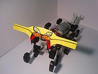
| + | LionHell literally means "lion hell", also translated as | ||
| + | Hellish Lion. Consequently, it was a must try and give it a feline aspect, | ||
| + | despite the bar sensory very long which is the head of the robot. | ||
| + | For this reason it was chosen as an example the Royal Bengal tiger | ||
| + | (Panthera tigris tigris), the tiger more widespread and more common, because we had practical problems in trying to create a real crest | ||
| + | around the head. | ||
| + | The new face is made from a plastic material, very lightweight, which allows | ||
| + | beautify LionHell II without increment excessively the weight, | ||
| + | while the colors were applied using permanent markers, leaving | ||
| + | sufficient space for the central sensor (and this is the reason of the mouth | ||
| + | arc). | ||
| + | |||
| + | [[File:Face LionHell.jpg|900px]] | ||
Revision as of 17:25, 8 April 2015
| Title: | LIONHELL MCMILLAN II: RIPROGETTAZIONE DI UN ROBOT ESAPODE BIOLOGICAMENTE ISPIRATO PER AREE MORFOLOGICAMENTE INSTABILI | [[Image:|center|300px]] |
|---|---|---|
| Description: | Hexapode wheg robot | |
| Tutor: | Giuseppina Gini | |
| Start: | 01/09/2014 | |
| Number of students: | 1 | |
| CFU: | 20 |
CHANGES IN PROGRESS
LionHell McMillan II is an hexapode wheg robot. LionHell McMillan has been developed in a Master Thesis work in Robotics and Artificial Intelligence by Vittorio Lumare ( http://airlab.ws.dei.polimi.it/index.php/LionHell_McMillan )
and it has been modified and improved in a Master Thesis work in Robotics and Artificial Intelligence by Alessandro Rosina (changing the name from "LionHell McMillan" to "LionHell McMillan II").
Info about Thesis
TItle : LIONHELL MCMILLAN II: RIPROGETTAZIONE DI UN ROBOT ESAPODE BIOLOGICAMENTE ISPIRATO PER AREE MORFOLOGICAMENTE INSTABILI
Robot Name: LionHell McMillan II
Supervisor: Giuseppina Gini
Correlator: Vittorio Lumare
Author: Alessandro Rosina
Area: Robotics and Artifical Intelligence
Start date: 2014/09/10
End date: 2015/04/29
Contents
State of the Art
Wheg
The locomotion system is the key element that allows the robot to interface and explore the surrounding environment and requires a careful choice that meets the requirements of handling, mechanical simplicity and fluidity motion, ensuring, in this case, the possibility to move easily on rough terrain, overcoming obstacles of small and medium size.
Definition of the Wheg
The Wheg are a mechanism of locomotion for robots that combine simplicity of movement of a wheel with the ability to scale and to overcome obstacles arising from the use of the legs. The acronym derives by the combination of words wheel and leg and mechanically it consists of a central rotary axis and which are connected one or more bars which perform the function of the legs. The operation of a Wheg is extremely simple: the three legs are connected to a central axis that rotates on itself and the point of contact with the ground is made from the end of the leg.
Wheg vs Wheel
The superiority of Wheg comparison to the use of a simple wheel is easily demonstrated:
- Consider a wheel that is about to face an obstacle placed on the floor, much smaller than the radius the wheel itself;
- Once the wheel comes into contact with the obstacle, the clutch that is generated will force the point of contact to remain in the same position and while the torsion of the wheel will continue to act, the point contact will function as a pivot. If the power of the engine will be enough the result will be that the wheel will walk across continuing in its path;
- Now consider a similar situation, in which, however, the obstacle that wheel must be facing the same overall height of its radius (h similar to r). In this case the contact point is on the side of the obstacle, and not above as in the previous case and the clutch that you should come and create so that it can be climbed should be such that allow the robot to move in a vertical manner with respect to the obstacle. Typically, this situation is not a realistic scenario and the experiment result will be that the wheel will start to slip on the spot, continuously changing the point of contact with the obstacle. Due to the fact the wheel would fail in this scenario, the wheel would fail for all scenarios where h > r as the contact point will always be on the side of the obstacle and not above.
Consider now the previous example, in which h is similar to r, but where in place of the wheel there is a Wheg three legs (in figures can be observe the presence of a circle around the Wheg: this circle is purely illustrative and serves only to relate the size of Wheg compared to those of the wheel):
- First, you can see the huge gap that the structure presents, space that will be used to your advantage: the structure is in fact able to exploit the empty space, facing the obstacle from above and not from the side as in the case of the wheel; </i>
- The force exerted by the engines and the twist of Wheg will do the rest, allowing the exploitation of the point of contact as a pivot to raise the Wheg frame and overcome the obstacle (you always remember that the circle only serves to show the trajectory of the three legs);
- Now consider another example, in where we have h > r, and in particular the case in which h = 3/2 r (as there are 3 legs). In this extreme case the Wheg will not be able to overcome the obstacle: the ability to climb it depends on how the Wheg is capable of penetrating the profile of the obstacle. You can get this goal by reducing the angle between the two upper legs, but this undermine the structure of Wheg making unstable.
From this analysis it is possible to highlight the main advantages and disadvantages of using a Wheg:
- Pro: the ability to climb obstacles of greater height than those addressed by a wheel having the same radius;
- Pro: the speed of movement of the robot is still high;
- Pro: the greater simplicity of construction and control compared to a leg, which must necessarily be controlled by two or three actuators;
- Cons: The land on which it moves must be rough, in order to do strength and be able to overcome the obstacle;
- Cons: Legs too thin could sink surfaces soft or non-rigid, such as sand or mud, due to the reduced contact surface;
- Cons: If your legs hit moving parts, such as long grass or cables very thin, the Wheg could be twisted, latching and risking damage to the robot in the case where the motors trying to do too much force to break free.
Control and Mobility in LionHell II
Wheg in LionHell II
The whegs are a mechanism of locomotion for robots that combine
simplicity of movement of a wheel with the ability to scale and to overcome obstacles arising from the use of the legs. The acronym derives
by the combination of words wheel and leg, and mechanically consist of a central rotary axis which are connected one or more bars
which perform the function of the legs.
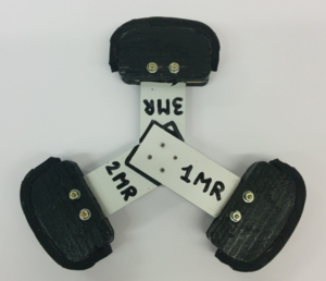
LionHell II has a total of 6 Wheg and each Wheg is composed of 3 bars arranged at 120° apart from each from the other, the ends of which is
mounted a foot slightly curved so as to ensure a secure grip on the ground. The movement of Wheg is simultaneous and each Wheg is controlled
by an independent motor that works in continuous mode, ensuring a smooth motion and robot suitable for every situation.
The Wheg that owns LionHell II is characterized by:
- a structure baseline, aluminium, guarantees the point of contact with the central hub;
- a basal structure of the foot, wood, molded according to an embodiment curve so as to adapt better to the ground and avoid jolts;
- the foam, in contact with the foot structure, reduces shocks of the robot in contact with the ground;
- rubber, in direct contact with the ground, protects the foam wear and allows the robot to move easily on any surface area;
- the symbol allows to easily identify the components of the Wheg and position of the leg in the same robot;
- the outline contour allows to understand intuitively the position with which the other members of Wheg be mounted.
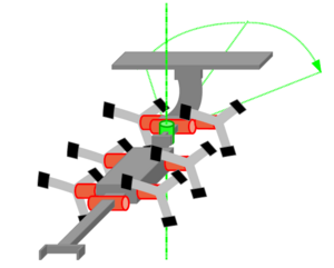
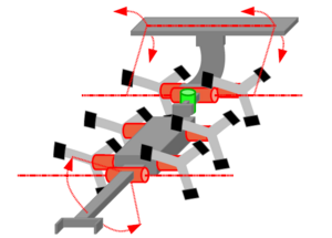
- the movement of Wheg: each wheg has 1 degree of freedom, for a total of 6 degrees of freedom;
- the movement of the joint motor and tail, each of which adds 1 degree of freedom, for a total of 2 degrees of freedom;
- the central passive joint which was added later, and the green lines trace a possible movement of the front part of the robot.
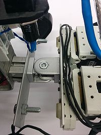
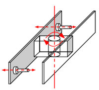
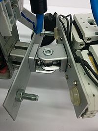
- a connecting member which allows rotation of a part of the body of LionHell II;
- a pair of metal bars at the two ends of the connecting element, which are part of the security system;
- two screws at the ends of the bars, their role is to define the angle of maximum rotation of the joint.
- two motors in position mode, which allow the tail to bend and to force the tip when its intervention is required;
- the total length of the queue, proportional to the length of the body;
- the response of the tail which operates only when the robot is preparing to face major obstacles, recognizable by sensors head.
- the structure of the queue has been reinforced, in order to avoid that the new tail is damaged over time because of the force developed by engines and the same weight of the robot;
- the strength of the joint that allows the new queue was moving increased, using two motors in parallel that allow LionHell II to move with greater ease while facing large obstacles.
- a 9 V battery and 250 mAh which is the power;
- an XBee Explorer Regulated that deals with the tension adjustment 3.3V, the signal conditioning and the basic activity indicators and converts the signals from 5V to 3.3V in order to connect the system to any XBee module;
- an XBee 4214A which plays the role of transmitting the signals received in input and communicates to the XBee installed on the body of LionHell II;
- a three-axis analog accelerometer ADXL335, with card detection +/- 3g devoid of voltage regulator (the input voltage must be between 1.8V and 3.6V dc);
- a circuit breaker switch that plays the role of power switch ON and OFF;
- a red button unstable normally open, which allows the use the remote control while pressing.
Compared to the previous model, we have kept the metal rod base and the rubber that was removed from the foot, since the movement of the same LionHell would irreparably damaged the Wheg and in particular the delicate foothold.
Central Passive Joint
This part will describe the role of the new central passive joint and the increase of the degrees of freedom that resulted.
Degrees of Freedom of LionHell II
The number of degrees of freedom (DoF) of a material point is the number of independent variables needed to determine uniquely its position in space (coordinates). The degrees of freedom is a term used to define freedom of movement of a robot in the three spatial skills, and the number of degrees of freedom of defining a robot configuration. LionHell II is a hexapod robot equipped with Wheg, tail, a coupling motor that allows him to lift the front in order to better deal with obstacles, and finally a central passive joint. In the figures you can observe the degrees of freedom of LionHell II:
The creation of a robot with a central joint in more passive arose from the idea to facilitate the movements when cornering and allow a more fluid movement. In the next subsection we will explain in more detail the joint that has been added.
Central Passive Joint of LionHell II
LionHell II is equipped with a passive joint central, whose role is to accompany the movement of Wheg facilitating the movement when the robot is going to bend. The passive coupling is constituted by:
The screws may be replaced with shorter or longer, at difference if you want a rotation angle lower or higher. In current state, the joint is able to rotate 10° to the right or to the left, while with the total absence of the screws the angle increases up to 30°. The addition screw was necessary as it was presented the risk that the front whegs were to collide with intermediate whegs, risking to block the robot in tight corners. The addition of the coupling passive was necessary because of the length of LionHell and the difficulty that this had in making some curves narrow, and the basic idea was to simulate, in some respects, the hook present in the trailers and in trains, with the difference that in this case also the trailer is able to bend, thus facilitating the movement.
Tail
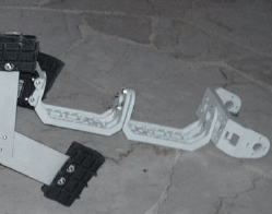
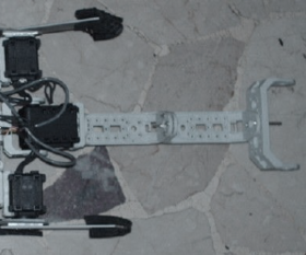
LionHell II is a mobile robot that has to face obstacles of small and medium size, and sometimes finds himself forced to having to overcome obstacles large. In order for this operation to be successful, it is necessary that the robot does not fall backwards because of repeated setbacks caused from the movement of the whegs seeking a foothold on which to do strength and lift the rest of the body of the robot.
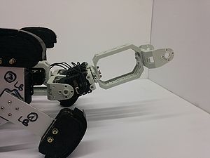
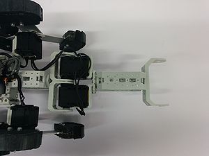
The addition of the tail ensures greater stability during the climbs and allows him to lift the body preventing the possibility of falling back. The morphological characteristics that allow the robot to move with greater ease, also facing major obstacles, are:
Compared to the original design, the tail has been modified to intensify the robot and increase the effectiveness and the force with which the tail presses on terrain, namely:
Remote Control in LionHell II
Remote controller
The figure shows the basic components of the remote control (excluding a button and the switch, which for practical reasons are not shown in figure, being incorporated into the external structure of the remote control). The remote control is made up of:
The movement of LionHell II is via the inclination of the remote control(pointing the tip of the magician's hat forward and with the red button upwards the robot is stationary, while raising or lowering the hat you can make it go forwards or backwards, and tilting the remote control to the right or the left, the robot rotates to the right or left, respectively), which detects a change of axes X and Y by means the accelerometer. The values are then passed to the XBee installed on remote control, which sends them directly to the XBee on LionHell II.
XBee of LionHell II
The goal of the XBee is to receive data from the remote control and send the data so received to the control board LionHell II, with the result that the control board doesn't notice even the existence of the XBee, as if it is reading data directly from the remote controller.
The figures show the XBee 4214A used LionHell II, mounted directly above the control board CM-510, at the center of the body of the robot, and the the components underlying the XBee. How it is possible to observe, are present (for each of the two digital inputs) a resistance and a capacitor: the reason is easily explained. The data transmitted from the XBee of the remote controller to the XBee of LionHell II are in analog form, but the inputs control board does not require a digital type wave square (obtainable via an inverting gate NOT, a Schmitt trigger, a capacitor and a resistor) but through a filter of low-pass type (which only requires the use of an RC circuit, based precisely on the use of a resistor and a dynamic element, the capacitor).
Changes to the firmware
Once the signal is started by the remote, it's been installed on the XBee on LionHell II and has been suitably modified to return the original values read initially by the accelerometer of the remote control, it is the turn of the control board CM-510. The board acts as if it reads the values directly from the accelerometer, doesn't even notice the existence of all the intermediate components, and discriminates on the basis of these values the actions to be taken. Below there is code of LionHell II reading the accelerometer values:
// Read Remote Controller via XBee using Virtual Wires
{
resultX = adc_start( 4 );
resultY = adc_start( 3 );
bRemoteButton = (PINE & BTN_RIGHT) ;
// printf( "\r \n resultX resultY button: %u %u %d " ,resultX, resultY , bRemoteButton ) ;
// BUTTON
if ( bRemoteButton )
{
walking = true ;
}
else
{
walking = false ;
}
//X
if ( resultX > 340 )
{
turnL = 0 ; turnR=0; // Go Fwd
} else
if ( resultX < 300 )
{
turnL = 1 ; turnR=1; // Go Bwd
}
//Y
if ( resultY > 340 )
{
turnR = 1 ; turnL=0; // Turn Right
} else
if ( resultY < 300 )
{
turnL = 1 ; turnR=0; // Turn Left
}
}
The code shows a first reading of the values X and Y of the accelerometer, saved in variables resultX and resultY, later is read the value of the red button by the variable bRemoteButton. In the case where the red button is pressed then the variable walking is set to true and based on the values of resultX and resultY is chosen the direction to take. The following code shows the behaviour of LionHell II after the reception of the signals of the accelerometer and after that has been chosen the action to be performed:
//Walking Actions
if ( walking==1){
if ( turnL && turnR) {
int i ;
for ( i =0; i <3; i++){//Go Backward
dxl_write_word ( whegs_sx [ i ] ,
P_MOVING_SPEED_L, 1624 ) ;
dxl_write_word ( whegs_dx [ i ] ,
P_MOVING_SPEED_L, 600 ) ;
}
} else
if ( turnL ) {//Turn Left
int i ;
for ( i =0; i <3; i++){
dxl_write_word ( whegs_sx [ i ] ,
P_MOVING_SPEED_L, 1624 ) ;
dxl_write_word ( whegs_dx [ i ] ,
P_MOVING_SPEED_L, 1624 ) ;
// dxl_wri te_word ( whegs_dx [ i ] ,
P_MOVING_SPEED_L, 0 ) ;
}
} else
if ( turnR) {//Turn Right
int i ;
for ( i =0; i <3; i++){
dxl_write_word ( whegs_sx [ i ] ,
P_MOVING_SPEED_L, 600 ) ;
// dxl_wri te_word ( whegs_sx [ i ] ,
P_MOVING_SPEED_L, 0 ) ;
dxl_write_word ( whegs_dx [ i ] ,
P_MOVING_SPEED_L, 600 ) ;
}
} else
if ( ! ( turnL + turnR) ) {// If not turning
go_fwd ( ) ; // Restart walking
}
} else {// Stop Walking
stop ( ) ;
}
In this case the choice of moving LionHell II is exclusively based on the values of walking , turnL (turn left) and turnR (turn right). In the case in which the values of turnL and turnR are both zero, then LionHell II continue straight (the function sets the speed dxl_write_word movement of each Wheg and its direction). In the other two cases, however, with the modifying of the values of turnL and turnR, the robot will make the decision to turn left or right by modifying the speed and directions of the whegs.
Design of LionHell II
Face of LionHell II
LionHell literally means "lion hell", also translated as Hellish Lion. Consequently, it was a must try and give it a feline aspect, despite the bar sensory very long which is the head of the robot. For this reason it was chosen as an example the Royal Bengal tiger (Panthera tigris tigris), the tiger more widespread and more common, because we had practical problems in trying to create a real crest around the head. The new face is made from a plastic material, very lightweight, which allows beautify LionHell II without increment excessively the weight, while the colors were applied using permanent markers, leaving sufficient space for the central sensor (and this is the reason of the mouth arc).

