TiltOne
TiltOne
| |
| Short Description: | Balancing robot |
| Coordinator: | AndreaBonarini (andrea.bonarini@polimi.it) |
| Tutor: | MartinoMigliavacca (migliavacca@elet.polimi.it) |
| Collaborator: | |
| Students: | |
| Research Area: | Robotics |
| Research Topic: | Robot development |
| Start: | 2008/03/01 |
| End: | 2010/04/20 |
| Status: | Active |
| Level: | Ms |
| Type: | Thesis |
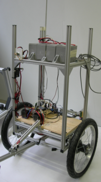
TiltOne is a two-wheels balancing robot that can keep itself in equilibrium while moving around. It's a bigger version of Tilty - our first balancing robot - as it is designed to be able to carry a quite high payload (up to 50kg) travelling at speeds of about 1.5m/s.
Contents
Mechanical project
Frame
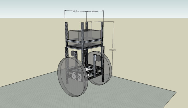
As the robot needs to keep the wheel axis just under it's center of mass to mantain the unstable equilibrium point, it's inertia should be high in the upper part of the frame and low at the wheel level, allowing the base to move while the center of mass holds - ideally - it's position. For this reason the batteries, that are the heavier component of the robot, are mounted at the top of the frame.
A preview of the robot structure was realized using Google Sketchup 6, giving a first idea about it's dimensions and components placement Media:Tiltone_2_-_completo.zip.
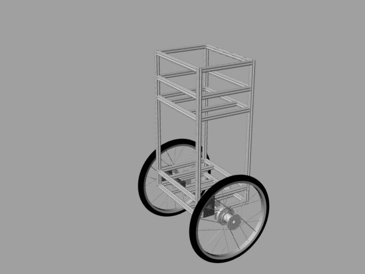
The robot frame is built using standard aluminium profiles (http://www.item.info) to allow future modifications and provide simple solutions to attach auxiliar devices.
Wheels and transmission
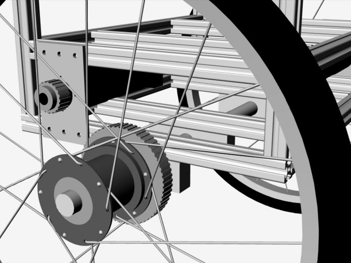
The mechanical project was then realized using Rinoceros 4.0 CAD. Apart from the robot frame, particular attention was dedicated to the design of the transmission and the wheel hub, that allow to use standard cross-bike wheels Media:Tiltone_3_Rhinoceros.zip.
The robot is actuated by two high-power electrical DC motor from Maxon Motor (www.maxonmotor.com) that provide torque to the wheels via a belt drive system.
Electrical project
Sensors
What the robot needs to control it's behavior are it's angle and angular velocity with respect to the direction of the gravitational force and the current speed of the wheels.
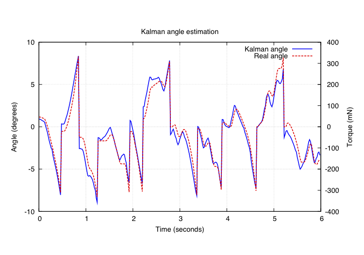
To acquire the robot angle and the angular velocity two sensors are used: an accelerometer (LIS344ALH by ST Microelectronics), that gives the components of the gravitational force along the vertical and horizontal axes of the frame, and a gyroscope (ADXRS150 from Analog Devices), that can directly measure the angular velocity with respect to the wheel axis. In order to reduce the influence of robot's movements sensed by the accelerometer, and to avoid the drift of the gyroscope readings, these two measurements are fused with a Kalman filter. The output of the filter is an estimate of robot's angle and angular velocity that tracks very well the real data.
Wheel's speed is obtained by two optical encoders (HEDS-5540 from Agilent) directly attached to the motor rotors, that allow to evaluate the rotor speed and to drive the motors with a closed loop controller.
Robot controller
The robot is controlled by a board built around a STM32 ARM7 Cortex M3 microcontroller from ST Microelectronics.
[Image:Tiltone board blocks.png]
The microcontroller acquires sensors data, apply a control law and commits a command to the motors. The software running on the ARM is real-time oriented, having periodic tasks constantly running at different frequencies and some interrupt-driven events that can modify the program flow. The board provides also a serial interface to an external PC used to program the microcontroller and a wireless Zigbee module allowing to communicate with the robot
