Talk:BCI based on Motor Imagery
How to set up BCI instruments
You’ll nedd:
- Electroencephalograph (with PCMCIA connector)
- Laptop (ensures that the AC adapter is NOT connected, for safety reasons)
- Electrodes or an Electrodes Cap (designed for the 10-20 system)
- Conductive gel
- Tape measure
- Adhesive tape
- Syringe
- Cotton fioc
- Abrasive electrode-gel
Before starting, be sure that the Electroencephalograph AC adapter is far away from the patient because 50Hz can interfere and destroy EEG signal. Don’t forget also to switch-off your mobile phone.
Now you can choose if you want to use an electrodes cap, or separated electrodes.
Electrodes Cap
Choose the suitable size for the patient, and then put the cap on his head in the correct position:
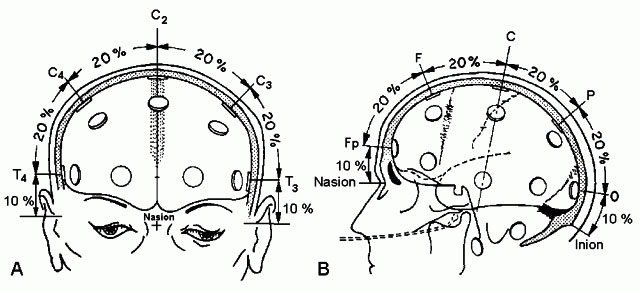
- measure his head size (from the nasion NS to the ….) this is the 100% of the measure
- now you can put the CZ electrode at 50% of the entire measure, and check the positions of the other electrodes.
- fill in the electrodes with conductive gel (use the syringe), take care that hair don’t disturb the skin-electrode contact.
- connect the cable to the Electroencephalograph.
Separeted electrodes
If you haven’t got an electrodes cap you can position them one by one following this figure, with the relatives measures of each electrode:
Connect the reference electrode to the forehead and the GND electrode to the right earlobe.
Before connecting one electrode, put a little bit of abrasive gel on a cotton fioc and scratch the portion of patient’s skin where you’ll put the electrode.
Fill in the electrode with a little bit of conductive gel, and put it on the skin, in the correct position.
Fix the cable with adhesive tape, and connect it to the Electroencephalograph.
If you want to eliminate EOG artefacts from your data acquisitions, you would record EOG signal putting 2 more electrodes, near the patient eye.
One electrode just over the eyebrow and one under the eye (REF) , like in the figure:
FIGURA elettrodi occhi
Connect the EOG cables to the A-Channel of the Electroencephalograph.
Now you can start Galileo Software and check if the correct values of impedance are measured. Click on the button “OHMMETER” in the upper toolbar, and the system will display the calculated value for each electrode, both in “graphical” form and in “numerical” one. Values under 10 KOhm are acceptable, values under 5 KOhm are very good. If your values aren’t under 10KOhm try to decrease them, filling the electrodes with more conductive gel until you reach acceptable values.
